Electrical Properties Dialog
Create and Edit Electrical Objects.

Introduction
The Electrical Properties Dialog is used to add / edit / create electrical objects for component models.
It is accessed from the Component Library Editor using the  toolbar button.
The type of electrical object you want to add is selected using the tabs near the top of the dialog.

These tabs provide access to the Power, Voltage, Current, Ports etc. electrical object types.
Along the bottom of the dialog are some configuration options.

The External Connection is checked by default and configures the electrical object to be an 'external' type.
Generally most electrical objects will be external except for those connected by a cable or wires.
Examples of this would be a depth sensor with 4-20mA output. The 4-20mA output circuitry is within the sensor body (internal) and is brought out to the world via a cable.
The Warn if not connected checkbox denotes whether the schematic checking logic should flag a warning if it is not connected to a compatible electrical object.
This can be usefull for some electrical objects such as Power Inputs. If there is no compatible power output connected to the power input, and Warn if not connected is checked then the software will indicate an error by:
- Rendering the Heads-up display in red
- Rendering the object's Overlapping points list entry in red
- Rendering the components Schematic Navigator entry in red
- List the disconnected input in the Schematic Report
The Warn if not connected configuration option can be applied to any electrical object including communication ports and miscellaneous objects.
Both the External Connection and Warn if not connected properties can be changed at any time using the context menu if you right-click on the electrical object.
The Close button exits the dialog without creating an electrical object.
The Place button will place the newly created electrical object onto the component editor symbol designer.
Applying Protocols, Measurements and Additional Functions (PMA) to Electrical Objects
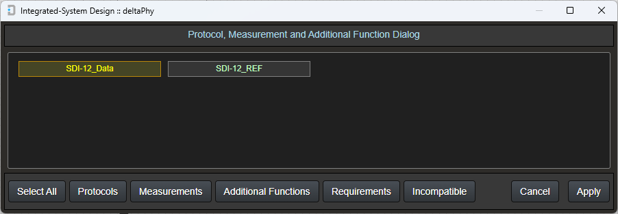
Applying PMA to electrical objects can be done after creating them, by right-clicking one of the object points and selecting Edit Measurements / Protocols / Additional Functions.

The PMA Dialog will open and indicate which of the electrical object's connections you right-clicked on.
In this case it was the SDI-12 data connection for an SDI-12 port.
You can opt to select the SDI-12_REF connection, but in the case of SDI-12, just apply it to the data connection as the _REF usually just goes to GND.
From there you can select to add / remove protocols, measurements, additional functions, requirements and incompatibles.
A Note on the Database
Integrated-system Design has two databases called 'Default' and 'Custom'.
The 'Default' database is the one downloaded from deltaphy.com and contains objects created by deltaPhy or objects created and shared by our community of users.
If you edit one of these objects and save it, or create your own, it will be saved in the 'Custom' database.
Some objects in this Electrical Properties dialog are sourced from the database.
These objects are: Ports, Wires, Cables, Connectors, and Misc Objects.
('Additional Functions' and 'Protocols' are also stored in the database, but they are not relevant to the Electrical Properties dialog).
When displaying information about any of these objects or placing them in the component, the software will favor any objects in the 'Custom' database if they exist.
The following sections will explain the various screens within the dialog.
Power Input
This is used to create a power input for a device.
To access select the
Some devices have more than one power input and you can create as many as you need for the component.
The power input can be AC or DC. This is selected using the AC/DC dropdown box.
The required fields are Mininum and Maximum voltages. This defines the voltage input range for the device.
If the component requires 9-40VDC then the minimum voltage would be 9 and the maximum would be 40.
The Current Draw field is optional and can be defined if the current draw is known.
The Device Can Sleep field is also optional. If the checkbox is selected then an additional input field will become visible which is Sleep Current and defines the current draw while the unit is in low power mode.
Power Input
Power Output
This option is similar to power input except, of course, its direction is an output.
To access select the
The minimum and maximum output range can be defined along with the current output capacity (optional).
For a device such as a sealed lead-acid (SLA) battery, the minimum might be 12 and the maximum 13. (or you just make them both 12V)
AC or DC can be selected using the AC/DC dropdown box.
Power Output

Digital Input
The digital input object has the same AC/DC selection as the power objects.
This configuration is accessed by clicking the
The required fields are Low and High logic level voltages.
Other parameters can be defined, if known, such as Maximum Voltage, Input Impedance, whether the input has a pull-up resistance, and if so, what it's value is (if known).
There is also an optional Frequency Limit which is taken into account by the Guidance System. In this context, if a digital output runs at for example the 1MHz range and this input has a 100kHz limit, then the guidance system will not show the two objects as compatible.
Digital Input

Digital Output Source
This digital output produces a voltage when active (high).
Digital Output Source configuration options are accessed using the
The logic LOW and HIGH levels are defined using the Source Logic Low and Source Logic High Voltage fields.
Optional parameters are:
- Source Current - how much current can the output supply.
- Frequency Limit - the guidance system and schematic checking logic will take this into account when checking for compatible inputs.
Digital Output Source

Digital Output Sink
This digital output 'sinks' or 'pulls' the output to it's reference connection (usually ground).
Digital Output Sink configuration options are accessed using the
Optional parameters are:
- Sink Current - how much current the output can sink to ground.
- Sink Max Voltage - the maximum voltage that the output can tolerate.
- Frequency Limit - the guidance system and schematic checking logic will take this into account when checking for compatible inputs.
- Contact Closure - creates a contact closure output for a tipping bucket rain gauge or pulse flow meter etc.
Digital Output Sink

Digital Output Push-pull
This digital output is a combination of Source and Sink where the output can drive a voltage and also pull to ground.
This output is accessed using the
The combined parameter set for Source and Sink are available for this output.
Digtal Output Push / Pull (Source / Sink)

Digital Input Contact Closure / Opto-coupler
This type of input can be modelled using a digital input with pull-up resistor, but it is easier to create a contact closure using this selection.
This input is accessed using the
This type of digital input is compatible with tipping bucket rain gauges, flow meters and any other output which is a contact closure.
If the "Opto-coupler"" check box is checked, an optional input field "Trigger Voltage"" and "Reverseable"" check box are displayed.
The Reverseable checkbox will create a reverseable opto-coupler input (either two LEDs wired back-to-back or a rectifier circuit to feed a single LED with the correct polarity).
Contact Closure Input

Digital Input with Opto-coupler Selected

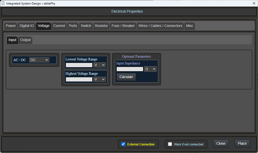
Voltage Input
This electrical object creates a voltage input useful for sensor inputs or general voltage sense inputs.
To access the voltage input object, use the
The voltage range can be configured using the Lowest and Highest voltage range fields.
An optional input impedance can be added. If the impedance is unknown but the current limit is known, use the Calculate button which will produce the following dialog:
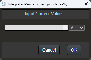
By entering the known current (I) value, the impedance will be calculated with Ohms Law using the Highest Range voltage field: R = V(highest) / I
Voltage Input
Voltage Output
Voltage Outputs are similar to Power Outputs, but these objects (voltage outputs) are designed more for sensor outputs.
To access the voltage output object, use the
Here you can select the voltage output range and also an optional maximum current parameter.
In the case of the Vaisala HMP110 Humidity and Temperature probe, the output range could be: 0 - 1VDC, 0 - 2.5VDC, 0 - 5VDC or 1 - 5VDC depending on the variant.
Voltage Output

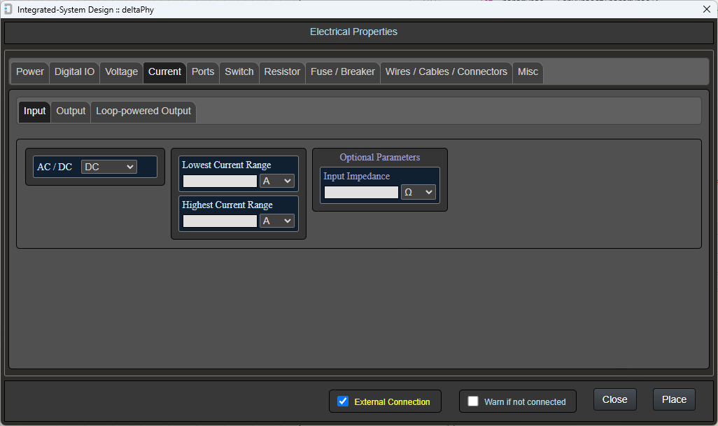
Current Input
Current Inputs accept current ( I ) as an electrical input. They are usually voltage inputs (ADC) with a low value shunt resistor in parallel to convert current to voltage.
To access the current input object, use the
Configure the current input with the minimum and maximum current range.
The optional input impedance can also be configured if known.
As an example, the YDOC data logger has 2 x 4-20mA current inputs. It's input impedance is 250 ohms due to the 250 ohm internal shunt resistor.
Current Input
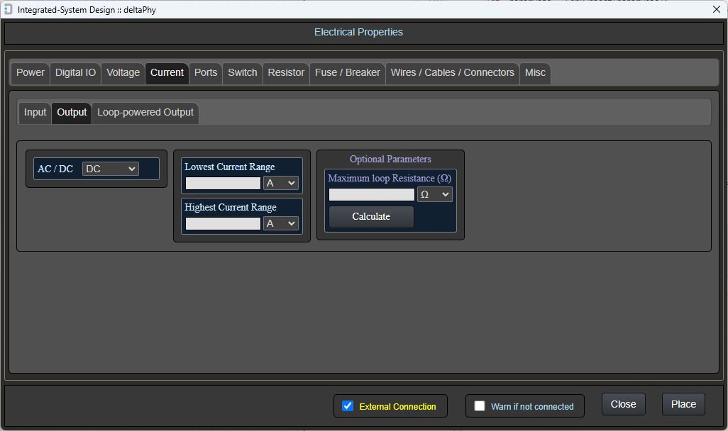
Current Output
Current Outputs output current ( I ) within a certain range.
To access the current output object, use the
Configure the current output with its minimum and maximum current range.
The optional maximum loop resistance can be configured if known.
This value denotes the maximum resistance in the wiring that carries the current ( I ) output.
This maximum resistance is dependant on the 'drive' voltage behind the current output.
If this 'drive' voltage is 24V, then the maximum resistance, and therefore the maximum length of wiring, will be higher (longer length wiring) than if the voltage was only 12V.
If the 'drive' voltage is known, Integrated-system Design can calculate the maximum resistance (using ohms law) if you click the 'Calculate' button.
This will display a voltage input dialog where you can input the 'drive' voltage.

Current Output
Loop-powered Current Output
This type of current output is usually found in 4-20mA output sensors.
To access the loop-powered current output, use the
Loop-powered current output devices accept a voltage input (often 9 - 40VDC) on one wire and output a current on another wire.
The path back to ground is through a shunt resistor and the signal is obtained as a voltage across this shunt resistor.
Usually, you would supply the Loop-powered device with a voltage and wire the current output wire to a data logger / PLC which has a suitabel current input.
This current input will have an internal shunt resistor which will complete the path to GND and also feed the voltage across the shunt resistor into a voltage input (ADC).
The Loop-powered Current Input object has a minimum and maximum current output range, a minimum and maximum voltage input range and an optional Maximum Loop Resistance value.
The Maximum Loop Resistance can be calculated using the 'Calculate' buton which will display a voltage input dialog.
Loop-powered Current Output

Ports
Ports are usually used for communication devices (RS-485 / Ethernet etc.) and can be accessed using the
An array of ports will be displayed which you can either select (if the port you need exists) or create using the 'New' button.
Ports can also be edited using the 'Edit' button.
A 'Create Additional Function' button is also displayed.
This button will add a selected port name to the 'Additional Functions' list in your resource database.
This means that if you create a component with a certain port you can add the port name to the component's functionality which will be displayed in the component heads-up display when the mouse is hovered over it.
This is handy when you hover the mouse on the component to see what functionality it provides to the circuit.
For example, you can hover your mouse over a DT-80 datalogger and instantly see that it has ethernet in the functionality it provides.
Communication Ports

While 'Ports' are usually used for communication objects such as RS-485 or Ethernet, they can also be used to model RTD (Resistive Temperature Devices) which can be 2, 3 or 4-wire devices.
Examples of Communication Ports
RS-232 Port

3 connections: Tx, Rx and REF.
REF should be connected to GND.RS-485 Port

3 connections: A, B and REF. REF should be connected to GND.
SDI-12 Port

2 connections: Data and REF. REF should be connected to GND.
We have encountered debate on whether RS-485 needs a GND connection or not.
In many circumstances, RS-485 does not need a GND connection because of the differential nature of the A and B connections.
In some cases (and we have encountered these) the ground potential of one RS-485 port may be several volts different from the other and communication may fail. In these cases, a GND connection will aid communication.
Creating Ports
Creating an RS-232 Port

Clicking the New button in the port dialog will display this screen.
Type in a port name for example RS-232. If this new port is a variation on an existing RS-232 port, add some additional text to differentiate it from exisiting ports. For example if you type (2) into the additional text the port type will still be RS-232 but will exist along side the original RS-232 port as RS-232(2). The ports will be compatible but the Additional Text just allows for variations.
Use the  button to add port connections.
Examples of these might be: Tx, Rx, REF (usually connected to GND). The  button is a quick way to add a REF connection.
Next, select one of the port connections and click the  button.
Edit Port Properties

If you select the Rx connection and open the Properties dialog, select the port connections on the other port that this Rx connection will connect to.
In this case, Rx could connect to both Rx and Tx on the other port.
The Rx connection on one RS-232 port can be connected to either a Tx or Rx connection on another RS-232 port.
Also, you wouldn't connect either to the REF connection as this normally goes to GND.
Next select, in the lower half of the dialog, which connection is required by this Rx connection on the other port. In this case, the REF connection is required.
This is because the Rx connection needs a reference to GND.
In the case of RS-485, the A connection connects to A on the other port and requires B on the other port. It may also require a GND reference.
Have a look at the example ports supplied with integrated-system Design.

If you selected the Tx connection, it can only connect to an Rx connection on another RS-232 port. You can't connect a Tx on one RS-232 port to the Tx on another.
The Tx connection also requires a GND reference so select REF as a requirement when adding properties to the Tx connection.

The REF connection connects to REF and also requires REF so it should be selected in both top ('connects to') and bottom ('requires') screens.
Editing Ports
Editing an RS-232 Port

The Edit Port dialog has a name field which in this case is RS-232
There is also an Additional Text field.
This field was created to allow variations on ports.
For example, you may have a device with an RS-232 communication port which supplies Rx, Tx and GND connections.
There will be other devices that also provide the CTS and RTS connections.
Both ports are still RS-232 and will most likely be compatible, so the Additional Text allows you to create other ports with the same communication type, but with variances.
Example RS-232 port with (2) as alternate text: RS-232(2) which includes the CTS and RTS signals.


Select a port connection and click the button to configure the connection.
Add Properties Dialog
Edit a port connection
In this example, the selected connection is Rx
Select Rx and Tx in the top section because Rx can be connected to either in a schematic drawing.
In the bottom section, select REF because Rx requires a reference to function correctly.
Switches / Breakers / Connector Links
Switches are accessed using the
Here you can configure the maximum voltage and current rating and the number of poles / throws.
When hovering the mouse on the Common connection of a switch, the overlapping points display will show all other connections connected to all other switch connections.
While this isn't possible in real terms, it is there to provide you with information about all possible connections the switch common could make.
You can apply AC and DC properties to the switch / breaker.
The optional 'Is Breaker' checkbox under the DC and AC properties allows you to apply the term 'Breaker' when the mouse is hovered on the object.
This helps to indicate that the intended use of the 'switch' is to be a breaker rather than a normal switch.
The 'Is Connector Link' checkbox is used to model a connector link such as a din rail mounted connector / terminal block.
Switch SPST

Switch Double Pole, Triple Throw

Resistors
Resistors are included with the intention to provide current (I) to voltage (V) conversion to allow 4-20mA current outputs to be compatible with analog voltage inputs.
This feature will be available in future versions of integrated-system Design and will be an addition to the Guidance System so current (I) outputs can be shown as compatible with voltage (V) inputs.
Resistor

Fuses
Fuses are a common and important component in any integrated / automation system.
You can apply AC and DC properties to this object.
In the schematic editor, this component will show connected electrical objects on both sides of the fuse / breaker to indicate the expected electrical connections. This is so the designer can see all connections through the fuse / breaker.
These connections are displayed in the Overlaping Points list at the top right of the window.
In the layout module the fuse / breaker won't indicate electrical connections from one fuse connection to it's other connection because the layout editor is used to design wiring layouts only.
Fuse / Breaker

Wires
Wires can be created and edited in this screen.
The 3 parameters: Resistance / km, Current Limit and AWG can be added / edited.
This provides information to the schematic designer about the type of wires they are placing.
The graphical size and color of the wire can be edited in all three of the main modules: Component Library, Schematic and Layout Editors
It is intended in future releases of integrated-system Design, for these parameters to provide warnings if wire / cable lengths may be too long for some connections (e.g) 4-20mA current loops etc.
Wires

Editing Wires

The Wire Manager dialog is used to edit wires.
You can define the Wire Name, Wire Resistance (per km or per ft), Max Current and AWG for the wire.
Note: The wires in this image were created for testing. You can add wires you use with correct amperage and AWG properties.
Cables
Cables are 'collections' of wires.
You can add any of the pre-defined / user-defined wires into a cable.
The graphical size and color of the cable and it's individual wires can be edited in all three of the main modules: Component Library, Schematic and Layout Editors
Hovering your mouse over one cable wire will indicate all electrical connections on that wire including at the other end of the cable.
Cables are also able to provide a 'fixed length' attribute which is used in the layout editor: if a cable is longer than it's fixed-length value, it will flag an error because it means the cable is longer than it's physical size.
Cables (hovering on 2-core containing different wire types)

Cables (hovering on 9-core)

Editing the 9-core Cable

The Cable Manager dialog is used to edit cables.
You can define the Cable Name and whether it is Fixed Length or not. A fixed length cable has a defined length. In the Layout Editor if you draw the cable longer than this Length an error will be flagged.
The Select Wires (click to add) section contains all wires defined in your resources. Clicking any of these wires will add them to the Selected Wires (click to remove) section. Clicking any of these will remove them from the cable.
At the bottom left of the dialog there is a Wire Count which indicates how many wires you have selected.
Note: The wires in this image were created for testing. You can add wires you use with correct amperage and AWG properties.
Example Cable Structure
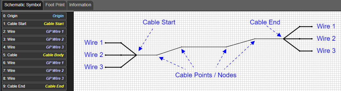
A cable object consists of a Cable Start object, a Cable End object, a Cable (middle) object where the cable Points / Nodes reside, and a set of Wires for the start of the cable and a set of Wires for the end of the cable.
Cable Wire Hover Example 1

Wires connect objects. Hovering on one wire of a cable will show other connected objects.
In this case, the Overlapping Objects display is showing the wire being hovered on and also the wire at the other end of the cable.
Cable Wire Hover Example 2

In this example the wire at the other end of the cable is connected to a Digital Input object on the Halytech MicroSpider II Logger
The Overlapping Objects display is showing the wire being hovered on, the wire at the other end of the cable and the digital input connected to the other wire.
Connectors
Connectors

This screen is where you can select from existing connectors or create your own.
Hovering your mouse over any of the connectors will produce a 'tool tip' displaying information about the connector.
Editing a Connector Object

Editing a DB9M connector object. It connects to an DB9F connector.
This is the same dialog used to create a new connector.
Specify the name, voltage rating, current rating and number of connectors.
Also, specify which other connectors this one can 'mate' with.
Connector Types
Terminal Block
The 'Terminal Block' style connector is used to simulate a terminal block.
You can create any electrical objects such as voltage input / output etc. and assign them to be Internal ('External' is false).
The terminal block will allow you to 'connect' to those electrical objects in the Schematic Editor.
Alternatively, you can just make your electrical objects External and not use this connector. This is what we did for the Campbell Scientific CR310 model.
Fixed Connector

This is the style of connector we used in our Netcom 5G Modem model.
The 'Connection Point' in this version of a connector is 'fixed' and can't be moved in the Schematic Editor
See the section below 'Connecting Connectors' to see how connectors 'conduct' and connect other electrical objects together.
Plug Style Connector

This is the style of connector we used in our ATMOS-41 Weather Station model.
The 'Connection Point' in this version of a connector is 'moveable' and can be moved in the Schematic Editor to 'connect' it to another connector.
See the section below 'Connecting Connectors' to see how connectors 'conduct' and connect other electrical objects together.
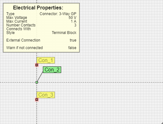
"Connecting" Connectors
Here are two connectors which happen to be the 'fixed' type.
Hovering the mouse over 'Con_3' highlights the other points in the connector, but there are no other objects connected (the Overlapping Points list is not shown because there are no other objects connected).

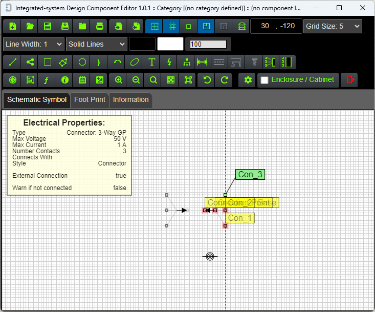
When the 'Connection Points' are touching, hovering the mouse over 'Con_3' shows that the corresponding connection in the other connector is now connected. The Overlapping Points list shows this connection.
'Con_3' in the other connector is also highlighted in red when the mouse is hovered on the right-hand connector's 'Con_3'.
Miscellaneous Electrical Objects
Miscellaneous electrical objects are used for convenience when you want to depict, for example, a communication port, but you don't want to include the detail.
We used a Miscellaneous electrical object as an RS-232 port on our DT-80 logger model. The Guidance system recognised it as a port and indicated other compatible ports with the same name (RS-232).
It can also be used in components such as SIM cards.
If you have some kind of electrical connection that is not a 'normal' voltage / current IO or port, you can just use a Miscellaneous object and apply whatever protocols, measurements and functions to it.
You can select whether the object is a connector or not also. We use a Miscellaneous objects to depict SMA plugs, RJ-45 Plugs and sockets etc.
Miscellaneous Electrical Objects

Editing a Miscellaneous Object

Editing an RJ45 Plug miscellaneous object. It acts as a connector (Is Connector is checked) and it connects to an RJ45 Socket.